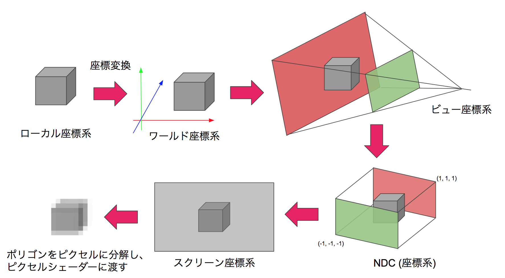
Figure 9.1: Flow of coordinate transformation
In this chapter, we will introduce a video projection method that allows you to experience the experience of being in the CG world by projecting images on multiple surfaces such as the walls and floor of a rectangular parallelepiped room. In addition, as the background, we will explain camera processing in CG and its application examples. The sample project can be found in Assets / Room Projection in Unity Project * 1 of Unity Graphics Programming, so please have a look. In addition, this content has been significantly revised and revised based on the content contributed to the "Mathematics Seminar December 2016" * 2 .
[* 1] Sample project https://github.com/IndieVisualLab/UnityGraphicsProgramming
[*2] https://www.nippyo.co.jp/shop/magazine/7292.html
Camera processing in general CG is processing that projects a 3D model of the visible range onto a 2D image using perspective projection conversion. The perspective projection conversion is a local coordinate system with the center of each model as the origin, a world coordinate system with the origin at a uniquely determined location in the CG world, a view coordinate system centered on the camera, and a clip coordinate system for clipping (this). Is a 4-dimensional coordinate system in which w also has meaning, and the 3-dimensional version is called NDC (Normalized Device Coordinates ), which is a screen coordinate system that represents the 2-dimensional position of the output screen. The coordinates of the vertices are projected in order.
Figure 9.1: Flow of coordinate transformation
In addition, since each of these transformations can be represented by one matrix, it is common practice to multiply the matrices in advance so that some coordinate transformations can be done by multiplying the matrix and the vector once.
In a camera in CG, a quadrangular pyramid with the apex at the camera position and the bottom surface at the camera orientation is called the viewing frustum, and can be illustrated as a 3D volume that represents the projection of the camera.
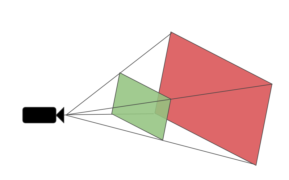
Figure 9.2: Frustum
If the viewing frustums of the two cameras share the apex and the sides are in contact, they will be connected visually even if the projection surfaces are facing different directions, and the perspectives when viewed from the apex will be the same. I will.
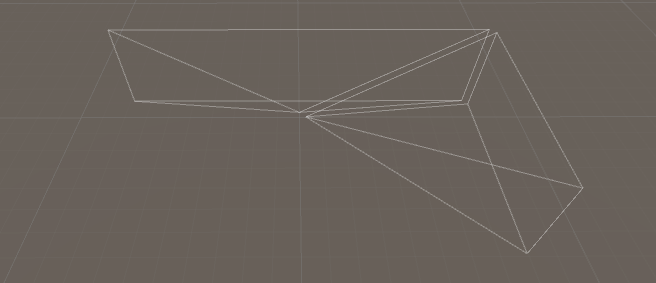
Figure 9.3: Touching frustum (placed slightly apart for clarity)
This can be understood by considering the view frustum as a set of innumerable lines of sight and thinking that the lines of sight are continuous (= images that are consistent in perspective can be projected). This idea was extended to five cameras, and the angle of view was adjusted so that the five view frustums shared the apex and were in contact with the adjacent view frustums, thereby corresponding to each surface of the room. You can generate a video. Theoretically, 6 faces including the ceiling are possible, but this time we consider it as a projector installation space and assume 5 faces excluding the ceiling.
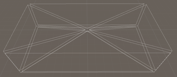
Figure 9.4: Five viewing frustums corresponding to the room
By viewing from this apex, that is, the location corresponding to all camera positions, you can view images that are consistent in perspective regardless of the direction of the room.
The projection matrix (hereinafter referred to as Proj ) is a matrix that transforms from the view coordinate system to the clip coordinate system.
It is expressed as follows by the formula.
C = Proj * V
Furthermore C each element of C_ {w} will position coordinates in NDC by dividing.
NDC = (\frac{C_{x}}{C_{w}},\frac{C_{y}}{C_{w}},\frac{C_{z}}{C_{w}})
In addition, C_ {w} = -V_ {z} (make Proj so that). Since the front direction of the view coordinate system is the Z minus direction, it is minus. In NDC, the display range is -1 \ leq x, y, z \ leq 1, and this conversion scales V_ {x, y} according to V_ { z} to obtain a perspective expression.
Now let's think about how to make Proj . Let N be the coordinate of the upper right point of nearClipPlane and F be the coordinate of the upper right point of farClipPlane in the view coordinate system .
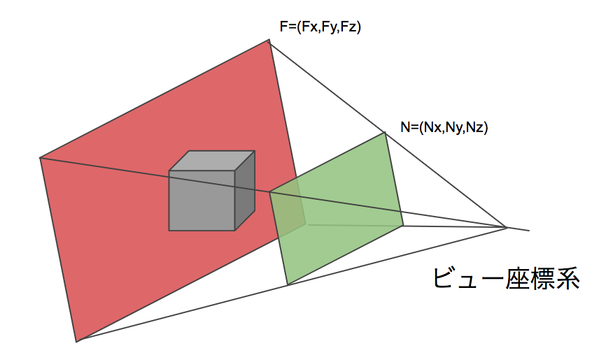
Figure 9.5: N, F
First of all, if you pay attention to x ,
Considering
Proj [0,0] = \ frac {N_ {z}} {N_ {x}}
If so, it looks good. Since the ratio of x and z does not change, any x, z such as Proj [0] [0] = \ frac {F_ {z}} {F_ {x}} can be used at the right end of the view frustum.
Similarly
Proj [1,1] = \ frac {N_ {z}} {N_ {y}}
Can also be obtained.
A little ingenuity is required for z . The calculation related to z in Proj * V is as follows.
C_ {z} = Proj [2,2] * V_ {z} + Proj [2,3] * V_ {w} (however, V_ {w} = 1)
NDC_ {z} = \ frac {C_ {z}} {C_ {w}} (however, C_ {w} = -V_ {z})
Here, I want to convert N_ {z} → -1, F_ {z} → 1 , so I put a = Proj [2,2], b = Proj [2,3].
-1 = \frac{1}{N_{z}} (aN_{z} +b),
1 = \frac{1}{F_{z}} (aF_{z} +b)
A solution can be obtained from this system of equations.
Proj [2,2] = a = \ frac {F_ {z} + N_ {z}} {F_ {z} -N_ {z}},
Proj [2,3] = b = \ frac {-2F_ {z} N_ {z}} {F_ {z} -N_ {z}}
Also, I want C_ {w} = -V_ {w}
Proj[3,2] = -1
will do.
Therefore, the required Proj has the following form.
Proj = \left(
\begin{array}{cccc}
    \frac{N_{z}}{N_{x}} &   0 & 0 & 0\\
    0   & \frac{N_{z}}{N_{y}} & 0 & 0\\
    0   &   0 & \frac{F_{z}+N_{z}}{F_{z}-N_{z}} & \frac{-2F_{z}N_{z}}{F_{z}-N_{z}} \\
    0   &   0 & -1 & 0
\end{array}
\right)
Some of the people who have dealt with projection matrices in shaders may feel uncomfortable with the contents so far. Actually, the handling of the projection matrix of Unity is complicated, and the contents so far are the explanation about Camera.projectionMatrix. This value is OpenGL compliant regardless of platform * 3 . This is why -1 \ leq NDC_ {z} \ leq 1 and C_ {w} = -V_ {w} .
[*3] https://docs.unity3d.com/ScriptReference/GL.GetGPUProjectionMatrix.html
However, Camera.projectionMatrix is not always used for perspective projection conversion as it is converted to a platform-dependent form when it is passed to the shader in Unity. In particular, the range and orientation of NDC_ {z} (that is, the handling of the Z buffer) are diverse and easy to get caught * 4 .
[*4] https://docs.unity3d.com/Manual/SL-PlatformDifferences.html
The shape of the bottom of the view frustum, or projection plane, depends on the camera's fov (fieldOfView) and aspect (aspect ratio) . In Unity's camera, the angle of view is published in the Inspector, but the aspect ratio is not published, so you need to edit it from the code. The code to calculate the angle of view and aspect ratio from faceSize (the size of the surface of the room) and distance (distance from the viewpoint to the surface) is as follows.
Listing 9.1: Finding the angle of view and aspect ratio
camera.aspect = faceSize.x / faceSize.y;
camera.fieldOfView = 2f * Mathf.Atan2(faceSize.y * 0.5f, distance)
                     * Mathf.Rad2Deg;
Note that Mathf.Atan2 () is used to find half the angle of fov with radian, doubled, and corrected to degree for substitution in Camera.fieldOfView.
Consider the case where the viewpoint is not in the center of the room. If the projection plane can be translated vertically and horizontally with respect to the viewpoint, the same effect as moving the viewpoint with respect to the projection plane can be obtained. In the real world, this corresponds to a function called lens shift that adjusts the projection position of the image with a projector or the like .
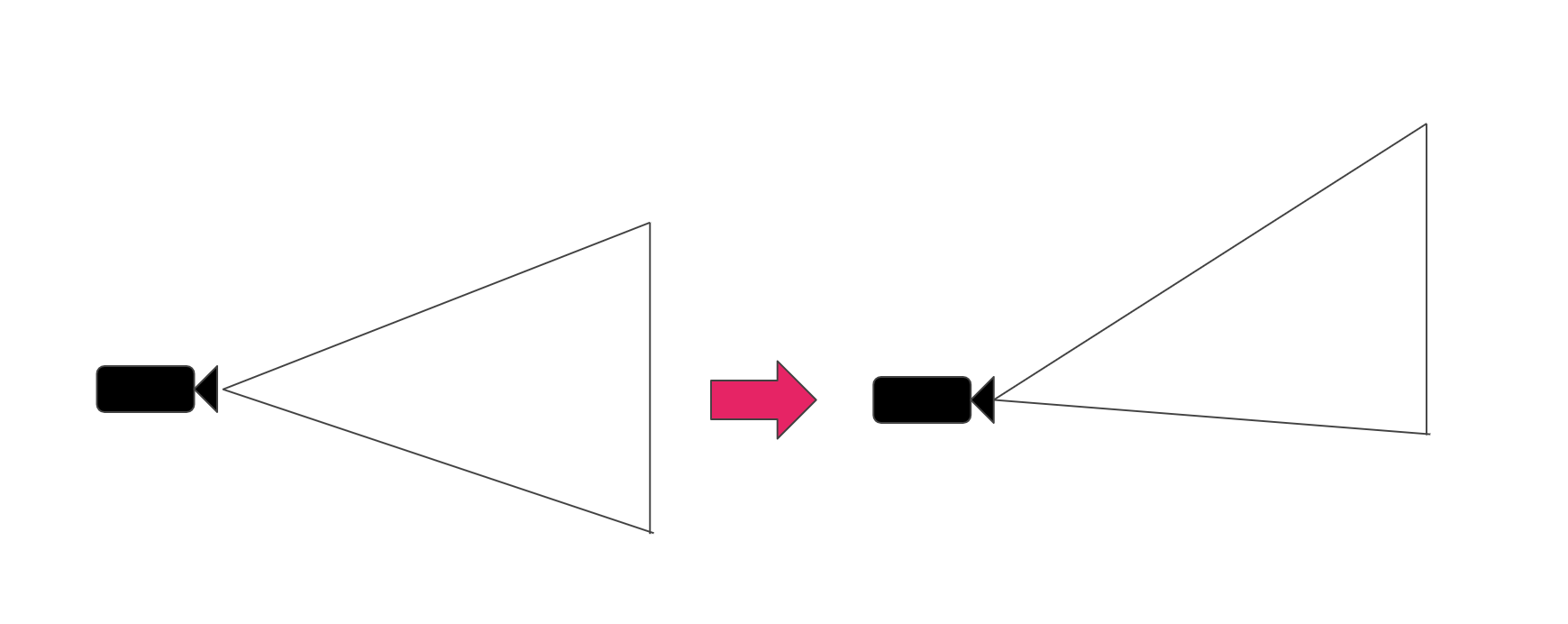
Figure 9.6: Lens shift
Looking back at the mechanism by which the camera performs perspective projection, what part of the lens shift is the process? When projecting to NDC with a projection matrix, it seems good to shift x and y. Let's look at the Projection matrix again.
Proj = \left(
\begin{array}{cccc}
    \frac{N_{z}}{N_{x}} &   0 & 0 & 0\\
    0   & \frac{N_{z}}{N_{y}} & 0 & 0\\
    0   &   0 & \frac{F_{z}+N_{z}}{F_{z}-N_{z}} & \frac{-2F_{z}N_{z}}{F_{z}-N_{z}} \\
    0   &   0 & -1 & 0
\end{array}
\right)
As long as C_ {x} and C_ {y} are out of alignment , I want to put something in the translation components of the matrix, Proj [0,3] and Pro [1,3] , but later C_ {w} Considering that it is divided by, the correct answer is to put it in Proj [0,2], Pro [1,2] .
Proj = \left(
\begin{array}{cccc}
    \frac{N_{z}}{N_{x}} &   0 & LensShift_{x} & 0\\
    0   & \frac{N_{z}}{N_{y}} & LensShift_{y} & 0\\
    0   &   0 & \frac{F_{z}+N_{z}}{F_{z}-N_{z}} & \frac{-2F_{z}N_{z}}{F_{z}-N_{z}} \\
    0   &   0 & -1 & 0
\end{array}
\right)
Since the unit of LensShift is NDC, the size of the projection plane is normalized to -1 to 1. The code looks like this:
Listing 9.2: Reflect lens shift in projection matrix
var shift = new Vector2(
    positionOffset.x / faceSize.x,
    positionOffset.y / faceSize.y
) * 2f;
var projectionMatrix = camera.projectionMatrix;
projectionMatrix[0,2] = shift.x;
projectionMatrix[1,2] = shift.y;
camera.projectionMatrix = projectionMatrix;
Note that once set to Camera.projectionMatrix, subsequent changes to Camera.fieldOfView will not be reflected unless Camera.ResetProjectionMatrix () is called. *Five
[*5] https://docs.unity3d.com/ScriptReference/Camera-projectionMatrix.html
It is assumed that the viewer's viewpoint position can be tracked in a rectangular parallelepiped room. Since the size of the projection surface of the viewing frustum can be translated by the method in the previous section, the viewing frustum is moved so that the viewpoint position is the apex of the viewing frustum and the wall surface or floor surface is the projection surface. You can ask for it. By making each camera such a viewing frustum, it is possible to create an image for each projection plane. By projecting this image into an actual room, the viewer will be able to see the CG world with perspective.
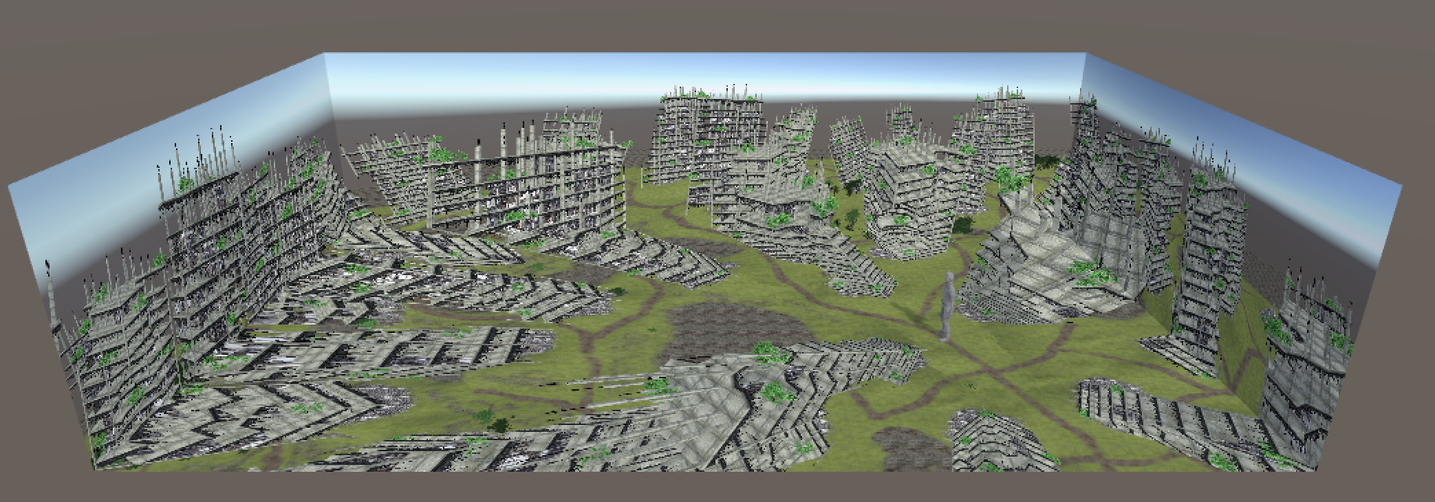
Figure 9.7: Room simulation (overhead view)
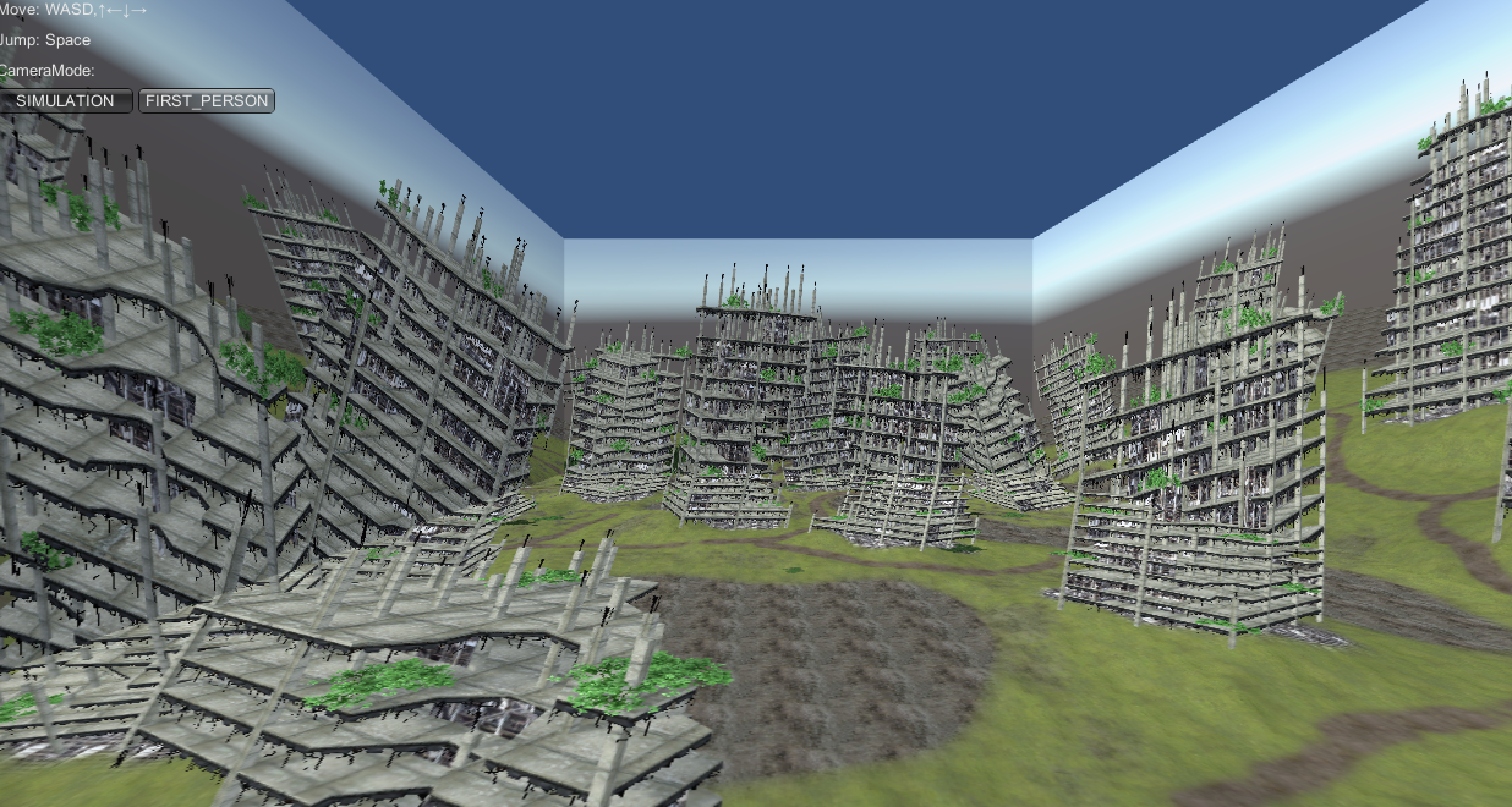
Figure 9.8: Room simulation (first person view)
In this chapter, we introduced a projection method that matches perspectives on multiple projection planes by applying a projection matrix. I think that it can be said that it is a VR with a non-approach similar to the recent HMD type in that it makes a wide range of the field of view a dynamically responsive image instead of placing the display in front of you. In addition, this method does not deceive binocular parallax or eye focus, so it may not be possible to see stereoscopically as it is, and it may look like a "moving picture projected on the wall". It seems that we need to devise a little more to increase the immersive feeling.
A mechanism called "CAVE" * 6 that combines the same method with stereoscopic vision is known.
[*6] https://en.wikipedia.org/wiki/Cave_automatic_virtual_environment